The design of a deep metal detector is similar to a regular one, with the exception of some technical details. It also differs in its increased sensitivity to metal objects, which makes it possible to detect them at greater depths compared to a simple metal detector. In addition, there is a selective search function, that is, the ability to find objects of a certain size without reacting to those that do not fit the parameters.
Diagram of a deep metal detector
It is quite simple, despite its apparent complexity. The metal detector consists of two parts – receiving and transmitting. The main device is a high frequency transmitter generator. Two loop antennas, one of which serves as a signal transmitter, the second as a receiver. They must be located strictly at an angle of 90 degrees to each other to prevent the receiving antenna from picking up the generator signals. When a metal object is found, the magnetic field created by the generator is distorted and subsequently picked up by the receiving antenna. In this case, the mass of a metal object is used as a source of radiation, sending the energy produced to the receiving antenna.
Metal detector receiver circuit
The transmitting device includes a thyristor with a power of 0.25 to 1 W and a sound generator with a frequency of 200 Hz. When a metal object is found, the operator hears a sound with a frequency of 200 Hz, the strength of which depends on the size of the object found and the distance to it.
A detector receiver whose oscillation circuit responds to a frequency of 120 kHz, and consists of two diodes. The amplifier can be absolutely any low-frequency generator that can be found in an old radio. An amplifier with transistors in the amount of 5-6 pieces is enough. A transistor is also used as a current amplifier for a pointer instrument, allowing the level of the received signal to be measured. That is, the device contains two types of indicators - visual and acoustic. The operating frequency is adjusted so as not to interfere with the operation of the signal receiver.
 Transmitter circuit
Required parts and tools for assembly
To assemble such a metal detector, you must first prepare a set of necessary parts and tools.
In the case of a pulse metal detector, approximate parts list will look like this:
- Electrolytic capacitors with a voltage of at least 16 V in the following capacities: 2 capacitors with a capacity of 10 μF, one with a capacity of 2200 μF, 2 pcs - 1 μF.
- Ceramic capacitors: 1 piece with a capacity of 1 nf.
- Film capacitors of the lowest voltage value, for example, 63 V - 2 pieces of 100 nf each.
- Resistors of 0.125 W: 1 k - one, 1.6 k - one, 47 k - one, 62 k - two, 100 k - one, 120 k - one, 470 k - one, 2 ohm - one, 100 ohm – one, 470 ohm – one, 150 ohm – one,
- Resistors of 0.25 W: 10 ohms - one.
- Resistors 0.5 W: 390 ohm - one
- Resistors 1 W: 220 ohm - one.
- Variable resistors: 10 k – one, 100 k – one,
- Transistors: BC 557 – one, BC 547 – one, IRF 740 – one,
- Diodes: 1N4148 - two, 1N4007 - one.
- Microcircuits: K157 UD2, NE555.
- Panels for each of them.
 Metal detector parts
From tools When performing work you will need:
- Soldering iron, tin, special solder, other soldering supplies.
- A set of screwdrivers, wire cutters, pliers and other plumbing tools.
- Materials for production printed circuit board.
Metal detector assembly steps
The process of assembling a deep metal detector with your own hands includes the following steps:
At the first stage, it is necessary to assemble the electronic part, namely the control unit.
The step-by-step process looks like this:
- Cutting PCB to the required size.
- Preparing a PCB design and transferring it directly to the board.
- Preparing the etching solution. It contains table salt, electrolyte and hydrogen peroxide.
- Etching the board and drilling technological holes.
- Tinning the board using a soldering iron.
- Next comes the most important stage in assembling the control unit. This is the selection, search and soldering of parts directly onto the board.
- Winding a test coil. There are several options for winding it. The simplest option is to use PEV wire size 0.5 and wind it 25 turns on a suitable frame with a diameter of about 19-20 cm.
The best option would be to solder everything directly, and after the setup is complete, select the necessary connectors and adapters. It is better not to twist, as this has a negative effect on the sensitivity of the device.
The second good option would be to make such a ring from twisted pair wire. You will need about 2.5 - 2.7 m of wire.
To achieve maximum sensitivity, do the following:
- Wind 25 turns of wire.
- Perform a test by cutting small pieces of wire and observing the increase in sensitivity.
- This must be done until sensitivity begins to decrease.
- Count the number of turns, wind the final version of the coil, adding 1-2 turns. Thus, the maximum sensitivity value is achieved.
Upon completion of the main work, the control unit, coil and other parts are fixed in place on the rod. The metal detector can be turned on and checked.
Possible problems during assembly
- The assembled device does not react to metal objects. The cause may be a breakdown of the diodes or transistor. Faulty parts need to be replaced.
- Excessive heating of the transistor. You should install a resistor of lower resistance, reducing it until the heating stops.
Assembly of this type of metal detectors is not too difficult, provided all rules and instructions are strictly followed.
Do-it-yourself metal detector - as the name suggests, such devices are made independently and are designed to search for metal objects and are used for a fairly narrow purpose. However, the methods for their implementation are quite diverse and constitute a whole direction in radio electronics.
Metal detector N. Martynyuk
The metal detector according to N. Martynyuk’s scheme (Fig. 1) is made on the basis of a miniature radio transmitter, the radiation of which is modulated by an audio signal [Рл 8/97-30]. The modulator is a low-frequency generator made according to the well-known symmetrical multivibrator circuit.
The signal from the collector of one of the multivibrator transistors is fed to the base of the high-frequency generator transistor (VT3). The operating frequency of the generator is located in the frequency range of the VHF-FM broadcast range (64... 108 MHz). A piece of television cable in the form of a coil with a diameter of 15...25 cm was used as the inductor of the oscillating circuit.
Rice. 1. Schematic diagram metal detector N. Martynyuk.
If a metal object is brought closer to the inductor of the oscillating circuit, the generation frequency will noticeably change. The closer the object is brought to the coil, the greater the frequency shift will be. To record frequency changes, a conventional FM radio receiver is used, tuned to the frequency of the HF generator.
The receiver's automatic frequency control system should be disabled. If there is no metal object present, a loud beep is heard from the receiver's speaker.
If you bring a piece of metal to the inductor, the generation frequency will change and the volume of the signal will decrease. The disadvantage of the device is its reaction not only to metal, but also to any other conductive objects.
Metal detector based on a low-frequency LC generator
In Fig. 2 - 4 shows a circuit of a metal detector with a different operating principle, based on the use of a low-frequency LC oscillator and a bridge frequency change indicator. The search coil of the metal detector is made in accordance with Fig. 2, 3 (with correction of the number of turns).

Rice. 2. Metal detector search coil.

Rice. 3. Metal detector search coil.
The output signal from the generator is fed to a bridge measuring circuit. A high-impedance telephone capsule TON-1 or TON-2 is used as a bridge null indicator, which can be replaced with a pointer or other external measuring device alternating current. The generator operates at frequency f1, for example, 800 Hz.
Before starting work, the bridge is balanced to zero by adjusting the capacitor C* of the oscillating circuit of the search coil. The frequency f2=f1 at which the bridge will be balanced can be determined from the expression:

Initially, there is no sound in the telephone capsule. When a metal object is introduced into the field of the search coil L1, the generation frequency f1 will change, the bridge will become unbalanced, and a sound signal will be heard in the telephone capsule.

Rice. 4. Diagram of a metal detector with an operating principle based on the use of a low-frequency LC generator.
Metal detector bridge circuit
The bridge circuit of a metal detector using a search coil that changes its inductance when metal objects approach is shown in Fig. 5. An audio frequency signal from a low-frequency generator is supplied to the bridge. Using potentiometer R1, the bridge is balanced for the absence of an audio signal in the telephone capsule.

Rice. 5. Bridge circuit of a metal detector.
To increase the sensitivity of the circuit and increase the amplitude of the bridge unbalance signal, a low-frequency amplifier can be connected to its diagonal. The inductance of the L2 coil should be comparable to the inductance of the L1 search coil.
Metal detector based on a receiver with the CB range
A metal detector operating in conjunction with a mid-wave superheterodyne radio broadcast receiver can be assembled according to the circuit shown in Fig. 6 [R 10/69-48]. The design shown in Fig. 1 can be used as a search coil. 2.

Rice. 6. A metal detector operating in conjunction with a superheterodyne radio receiver in the CB range.
The device is a conventional high-frequency generator operating at 465 kHz (the intermediate frequency of any AM broadcast receiver). The circuits presented in Chapter 12 can be used as a generator.
In the initial state, the frequency of the HF generator, mixing in a nearby radio receiver with the intermediate frequency of the signal received by the receiver, leads to the formation of a difference frequency signal in the audio range. When the generation frequency changes (if there is metal in the field of action of the search coil), the tone of the sound signal changes in proportion to the amount (volume) of the metal object, its distance, and the nature of the metal (some metals increase the generation frequency, others, on the contrary, lower it).
A simple metal detector with two transistors

Rice. 7. Scheme of a simple metal detector using silicon and field-effect transistors.
The diagram of a simple metal detector is shown in Fig. 7. The device uses a low-frequency LC generator, the frequency of which depends on the inductance of the search coil L1. In the presence of a metal object, the generation frequency changes, which can be heard using the BF1 telephone capsule. The sensitivity of such a scheme is low, because It is quite difficult to detect small changes in frequency by ear.
Metal detector for small quantities of magnetic material
A metal detector for small quantities of magnetic material can be made according to the diagram in Fig. 8. A universal head from a tape recorder is used as a sensor for such a device. To amplify weak signals taken from the sensor, it is necessary to use a highly sensitive low-frequency amplifier, the output signal of which is fed to the telephone capsule.

Rice. 8. Diagram of a metal detector for small quantities of magnetic material.
Metal indicator circuit
A different method of indicating the presence of metal is used in the device according to the diagram in Fig. 9. The device contains a high-frequency generator with a search coil and operates at frequency f1. To indicate the signal magnitude, a simple high-frequency millivoltmeter is used.
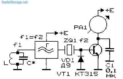
Rice. 9. Schematic diagram of a metal indicator.
It is made on diode VD1, transistor VT1, capacitor C1 and milliammeter (microammeter) PA1. A quartz resonator is connected between the output of the generator and the input of the high-frequency millivoltmeter. If the generation frequency f1 and the frequency of the quartz resonator f2 coincide, the needle of the device will be at zero. As soon as the generation frequency changes as a result of introducing a metal object into the field of the search coil, the needle of the device will deviate.
The operating frequencies of such metal detectors are usually in the range of 0.1...2 MHz. To initially set the generation frequency of this and other devices of similar purpose, a variable capacitor or a tuning capacitor connected in parallel with the search coil is used.
Typical metal detector with two generators
In Fig. 10 given typical diagram the most common metal detector. Its operating principle is based on the frequency beats of the reference and search oscillators.

Rice. 10. Diagram of a metal detector with two generators.

Rice. 11. Schematic diagram of the generator block for a metal detector.
A similar node, common to both generators, is shown in Fig. 11. The generator is made according to the well-known “three-point capacitive” circuit. In Fig. Figure 10 shows a complete diagram of the device. The design shown in Fig. 1 is used as search coil L1. 2 and 3.
The initial frequencies of the generators must be the same. The output signals from the generators through capacitors C2, SZ (Fig. 10) are fed to a mixer that selects the difference frequency. The selected audio signal is fed through the amplifier stage on transistor VT1 to the telephone capsule BF1.
Metal detector based on the principle of generation frequency interruption
The metal detector can also operate on the principle of disrupting the generation frequency. The diagram of such a device is shown in Fig. 12. If certain conditions are met (the frequency of the quartz resonator is equal to the resonant frequency of the oscillatory LC circuit with the search coil), the current in the emitter circuit of transistor VT1 is minimal.
If the resonant frequency of the LC circuit changes noticeably, the generation will fail, and the readings of the device will increase significantly. Parallel measuring device It is recommended to connect a capacitor with a capacity of 1 ... 100 nF.

Rice. 12. Circuit diagram of a metal detector that works on the principle of disrupting the generation frequency.
Metal detectors for searching for small objects
Metal detectors, designed to search for small metal objects in everyday life, can be assembled according to those shown in Fig. 13 - 15 schemes.
Such metal detectors also operate on the principle of generation failure: the generator, which includes a search coil, operates in a “critical” mode.
The operating mode of the generator is set by adjusted elements (potentiometers) so that the slightest change in its operating conditions, for example, a change in the inductance of the search coil, will lead to disruption of the oscillations. To indicate the presence/absence of generation, LED indicators of the level (presence) of alternating voltage are used.
Inductors L1 and L2 in the circuit in Fig. 13 contain, respectively, 50 and 80 turns of wire with a diameter of 0.7...0.75 mm. The coils are wound on a 600NN ferrite core with a diameter of 10 mm and a length of 100... 140 mm. The operating frequency of the generator is about 150 kHz.

Rice. 13. Circuit of a simple metal detector with three transistors.

Rice. 14. Scheme of a simple metal detector using four transistors with light indication.
Inductors L1 and L2 of another circuit (Fig. 14), made in accordance with the German patent (No. 2027408, 1974), have 120 and 45 turns, respectively, with a wire diameter of 0.3 mm [P 7/80-61 ]. A 400NN or 600NN ferrite core with a diameter of 8 mm and a length of 120 mm was used.
Household metal detector
A household metal detector (HIM) (Fig. 15), previously produced by the Radiopribor plant (Moscow), allows you to detect small metal objects at a distance of up to 45 mm. The winding data of its inductors are unknown, however, when repeating the circuit, you can rely on the data given for devices of similar purposes (Fig. 13 and 14).
Rice. 15. Scheme of a household metal detector.
Literature: Shustov M.A. Practical circuit design (Book 1), 2003
A metal detector is used to search for objects with certain electromagnetic characteristics, namely metals. In professional activities, this device is used by inspection services, archaeologists, geologists and professional treasure hunters. In addition, a metal detector is often used in construction, for example, to detect reinforcement, wiring and profiles in walls.
Professional equipment has a very significant drawback - very high cost, which varies depending on the detection depth, interface type and metal recognition function.
The need for a metal detector also arises among ordinary people. Often these are those who decided to try themselves as a treasure hunter. Unlike professionals, who are provided with equipment or provided by an organization, novice amateurs do not always want to purchase an expensive device. This is due to the fact that such a purchase will not be used for professional use and is unlikely to sell itself.
For an amateur who is just starting to work with these devices, a self-assembled metal detector may be suitable. Homemade devices are relatively easy to make; there are many on the Internet detailed instructions. Anyone can assemble a metal detector with their own hands if they have the desire and the required components for assembly; and their assembly can be done even by those who have little knowledge of radio installation. Homemade devices can have both relatively weak characteristics and not be inferior to expensive branded products. Before assembling the device, you need to know its structure and types.
In order to understand what kind of metal detector you need to assemble, you need to decide on the list of work to be carried out, as well as which metals will be the target of the search. Externally similar devices for searching for gold and construction work differ in design and technical specifications. The following general search device parameters exist:

Search discrimination can occur in three ways:
- Spatial, which indicates the location of the found object in the zone electromagnetic field, as well as its depth.
- Geometric, showing the size and shape of the found object.
- Qualitative, determining what properties the found material has.
Operating frequency range
Metal detectors operate in a certain frequency range:
- Ultra-low frequency, up to several hundred Hz. Powerful metal detectors that require high voltage, impressive dimensions, and computer signal decoding make these devices unsuitable for amateur use.
- Low frequency, up to several kHz. Enough simple circuits and design, good noise immunity and insensitive to the ground. They have penetration, depending on the supplied voltage, up to 5 meters. They react most acutely to ferrous metals and reinforced concrete structures.
- High frequency, up to tens of kHz. They have more complex circuits, but are less demanding on coils. Relative noise immunity and detection depth of up to one and a half meters. They work very poorly in wet and mineral soils.
- Radio frequency, used to search for non-ferrous metals, such as gold. Detection depth less than a meter in dry soils, are very critical to the design and quality of the coils used.
Classification by search type
There are many search methods, but many of them are applicable only in professional activities, and are not feasible in homemade devices. More applicable at home include:
- Without receiver (parametric).
- On the beats.
- Accumulation phase.
- Transceiver.
Parametric metal detector
These devices do not have a receiving coil or receiver, and detection of an object occurs due to its influence on the generator coil; changes in its parameters, such as the frequency and amplitude of the generated oscillations, are recorded by different possible ways. They are quite easy to assemble and have relatively high noise immunity. They are often used as magnetic detectors due to their low sensitivity.
Transceiver device
The device consists of transmitting and receiving coils, an EM vibration transmitter, and can also be equipped with a discriminator that will detect only certain metals.
 The coil creates an electromagnetic field; If there are materials in its zone that have an excellent electromagnetic field, the receiver picks them up and gives an audible signal about detection. If an object is detected that does not have electrically conductive properties, but has ferromagnetic characteristics, then it will distort the electromagnetic field due to shielding.
These devices achieve better performance in their operating frequency range, but their self-production requires a high-quality system of coils, which must be ideally positioned relative to each other.
A transmit-receive metal detector with one coil is called inductive. Its creation is simpler due to the fact that there is no need to select coils, but it is necessary to separate the secondary weak signal relative to the emitted primary one.
Phase sensitive device
These metal detectors are presented as pulse detectors with one coil or devices with two coils, each of which is influenced by a separate generator.
In the case of a pulsed phase-sensitive metal detector, the emitted pulses upon collision with the desired metal are delayed, and during an increasing phase shift, the discriminator is triggered and sends a signal. The closer the device is to the object, the more frequent the signals become. The popular homemade metal detector “Pirate” with metal discrimination works on this principle.
The principle of operation of a device with two coils is based on the fact that the electromagnetic fields of the two coils are synchronized and work in time; and when the field is distorted, desynchronization occurs and the discriminator begins to emit signals. This type of device is easier to manufacture than a single coil device, but the depth of possible detection is reduced.
Based on the harmonic principle
This device contains two coils: working and support. The reference oscillating coil is small, protected from extraneous interference, or stabilized by a resonator. The frequency of the working search coil depends on the presence of the desired objects in the radiation zone.
Before starting the search, they are tuned to match the frequencies and, as a result, a single-tone sound. A change in tone means that metal objects enter the zone of the electromagnetic field, and the size and depth of the object are determined from the level of change.
Metal detector coils
The main requirement for the quality of homemade devices is competent manufacturing of the coil and its reliable shielding.
 When creating a device, the device circuit is adjusted to the coil until optimal values are obtained. If the metal detector works with an incorrectly selected coil, it will have very poor performance. In this regard, when choosing an option for manufacturing, you need to carefully look at the description of the coil. If it is not complete enough, it is better to make another device.
The size of the coil is also important. Wide ones penetrate the ground deeper, but if large objects are detected, their signal will block potentially necessary small objects. Also, to increase detection depth, you need to have a wider coil.
It is common to use coils with a diameter of up to 90 mm when searching for profiles and fittings, up to 150 mm for small items, and diameters up to 600 mm for searching large-sized iron.
It would be ideal if the metal detector is designed to work with coils of different sizes.
Noise immunity
The reels catch well various types tips, and There are 2 common ways to increase noise immunity:
Baskets
These coils are available in flat and volumetric versions; they are stable, less sensitive to interference, and have high discrimination. For a beginner, it is easier to wind a flat reel.
Computer disks, plates and saucers can serve as its mandrel, and you can calculate the winding yourself. The volumetric option is to be wound without calculation using computer programs impossible.
Simple DIY metal detector
This version of a homemade metal detector consists of a signal decoder, a signaling device and a coil. To assemble it you will need:
- PIC12F675 chip or its analogs and programmer for firmware.
- Resonator at 20 MHz.
- Voltage stabilizer AMS1117.
- 15 pF and 100 nF ceramic capacitors, 10 µF electrolytic and 100 nF film capacitors.
- Resistors 470 Ohm, 10 kOhm.
- Sound emitter.

Soldering is carried out using a hinged or mounting method; a voltage of 9-12 V is required to power the circuit. The stabilizer controls the output 3.3 V.
The coil is wound on a 10 cm mandrel with a wire with a cross section of 0.3 mm. It is required to tightly wind 90 turns, and wrap the resulting structure tightly with tape and place it in a Faraday shield.
The result is a fairly powerful metal detector for deep searching, which can be set to discriminate: when detecting ferrous and non-ferrous metals, a sound of different frequencies will be emitted.
Professional metal detectors are often quite expensive and beyond the reach of amateurs. There are diagrams of metal detectors on the Internet; some of them can be assembled with your own hands, without any special radio installation skills or professional equipment. If desired, you can even assemble an underwater metal detector that will work equally both on land and in water.
In order for a self-assembled device to ideally meet all possible requirements, it is necessary to understand the design of the metal detector and decide on the type of search work that will be carried out with the device after its assembly. This will help you choose exactly the version of the metal detector that a novice treasure hunter needs.
In this article we will talk about one of the simple metal detectors, the assembly of which can be carried out using available Soviet radio components. These include transistors marked CT and MP, as well as resistors and capacitors from popular radio equipment. Most of the necessary parts can be found without problems in old radio devices.
The circuit consists of five nodes, the structure of which can be viewed in Figure 1:
- Master frequency oscillator, used to create a reference frequency.
- Search frequency generator. Its frequency will change when metal is found.
- Low-frequency amplifier to increase the signal difference of the generators.
- A node that produces sound.
- Power supply.
This device resembles a metal detector with two transistors, but it has an added sound amplifier, and, despite its simplicity, it has good metal detection performance. It is perfect for mass search and collection of ferrous metal. If you find radio components and a little time, you can easily assemble a metal detector using the example of this educational article.
Assembling circuit elements
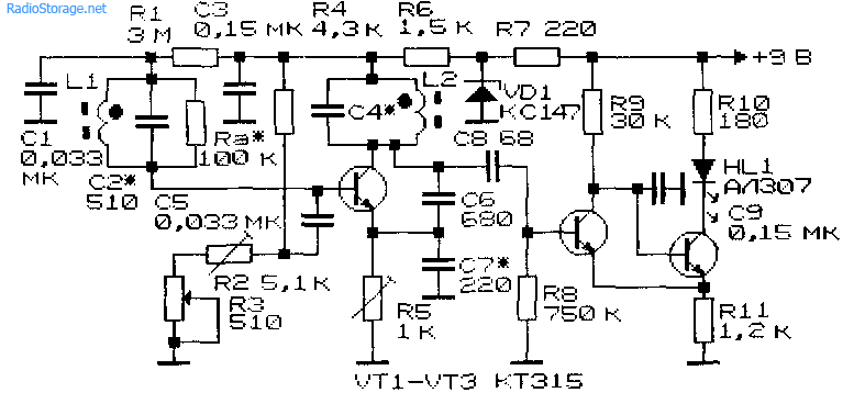
The circuit can be assembled on a one-sided foil-coated PCB. Guided by Figure 2, which shows the circuit of a metal detector using transistors, we count the number of connections and create the corresponding number of contact pads with a sharp object. After tinning, the board is ready for assembly of parts (Fig. 3). For better assembly, you can think over and draw a homemade printed circuit board.


Below is a list of required parts and instructions for some of them:
- 14 resistors with a power of 0.125 W. Denominations:
- R1, R5 – 100 kOhm;
- R2, R6, R11 – 10 kOhm;
- R3, R7 – 1 kOhm;
- R4, R8 – 5.1 kOhm;
- R9 – 6.2 kOhm;
- R10, R13 – 220 kOhm;
- R12 – 3.9 kOhm;
- R14 – 3 kOhm.
- 14 capacitors, preferably heat-resistant:
- Electrolytic at 6 V: C10, C14 – 47 µF; C12, C13 – 22 µF;
- Variable capacitors C7 – up to 10 pF / from 150 pF;
- Trimmer capacitor C8 – 6/25 pF;
- C1, C11 – 47 nF;
- C2, C6 – 4.7 nF;
- C3 – 100 pF;
- C4 – 47 pF;
- C5, C9 – 2.2 nF.
- Five transistors:
- 3.1 VT1, VT2 – KT315. As analogues you can use KT3102, KT312 or KT316;
- 3.2 VT3, VT4, VT5 – MP35. Can be replaced with MP from 36 to 38;
- 3.3 VT6 – MP39. MP from 40 to 42 are also suitable;
- 2 diodes D9Zh, or others - D18, D2, GD 507.
- Power supply 4.5 V in the form of three AA batteries. You can use a 9V Krona battery, but in this case it is necessary to change the electrolytic capacitors to a voltage higher than 9V.
- Speaker with resistance from 5 to 100 Ohms. Speakers from children's toys, intercom handsets, radios or a headset are suitable.
- Contact connector for battery (Fig. 4).
- Microswitch or toggle switch to turn off.

Metal detectors cannot work without coils that perform main role in the device. In the next paragraph of the article we will describe in detail their role in the work and the manufacturing process.
Creating Generator Coils
The primary coil L1 is exemplary and, together with capacitor C3, serves to create the reference frequency of the generator. The secondary coil L2 works in the same way, but it is made without a core. This allows metal objects to act on it and change the frequency of the generator, which leads to a difference in frequencies for the signal.
Below is how to make homemade coils without much difficulty.
For the frame of the L1 coil, you need a metal rod with a diameter of 8 mm and a length of 3 cm. You can use an antenna with a radio. Whatman paper must be wound around the rod. We do this to be able to adjust the frequency by moving the rod relative to the coil, so it is important that the Whatman paper fits very tightly to prevent spontaneous movement. After the final setup of the metal detector in the last step, you can fix the rod with glue. A sample coil is shown in Figure 5.

We wind the L1 coil with PEV wire with a diameter of 0.2 - 0.3 mm. We wind 110 turns on whatman paper strictly in one row, trying to avoid gaps or gaps between turns. At the 16th turn we make a tap without breaking the wire. After winding, you can varnish the wire, but you must ensure that the metal rod inside can move freely. We connect the wire according to the diagram.
The second coil L2 is made in the form of a rectangular frame measuring 12 x 22 cm. The frame can be made of plastic, plexiglass, plywood and other non-conducting material. We make a tray or assemble only a supporting rectangle into which the winding can be laid in bulk. Ready samples can be seen in Figure 6.

The wire, as in the first case, we choose PEV brand, but with a diameter of 0.4 - 0.6 mm. We wind 45 turns, making a conclusion on the 10th turn. After the metal detector is fully manufactured and configured, it will be possible to fix and insulate the winding with varnish. The connection to the circuit is made with a shielded cable with at least two cores. Such cables are used in high-quality audio equipment and in trunk communication lines, and they can also be purchased at an electronics store.
Making a metal detector design
First of all, you need to decide what material the bar will be made of. It is better to give preference to dielectric material to eliminate problems with the operation of the metal detector. There are many options: PVC pipe, telescopic fishing rod, wooden pole. When choosing, it is worth considering such indicators as weight, flexibility, disassembly ability, and convenience.
If you plan to spend a lot of time searching for metal, the light weight and comfortable armrest with handle will save you a lot of effort. But do not forget that lightweight material can bend. In the case of a PVC pipe, this can be compensated for by sand poured inside or additional supporting structures. With a collapsible rod there will be no problems with transportation. To implement this idea, you can visit a plumbing store and assemble an excellent metal detector with your own hands using various adapters (Fig. 7).

Once you have decided on the choice of rod, you need to attach the reel to it. Everything is simple here - no metal. Use plastic fasteners, pre-attached ears on the reel frame, adapters, or simply reliable glue.
We place the circuit in a plastic box. You can make small holes for the speaker for good audibility. The board, speaker, primary coil and battery box can be secured with glue. We place the box a meter from the search coil and fasten it in a convenient way - using plastic fasteners or glue.
At this point, you have assembled a simple transistor metal detector that needs fine tuning and testing.
Device setup
Setting up a metal detector involves creating the same frequency in both generators. When this result is achieved, the lowest, barely audible tone will be emitted from the speaker.
First, remove all metal objects from the range of the metal detector. We take into account concrete walls and floors, since they may contain metal reinforcement. We set all variable capacitors to the middle position. By changing the position of the rod in coil L1, we achieve the desired tone or lack thereof. During further operation of the device, we use capacitor C7 for adjustment. After setting up, we bring a metal object to different distances from the search coil and make sure that the metal detector is working.
If the metal detector does not work, we check the blocks and circuit parts. We start the test with transistors, and then check the diodes. To check the sound amplifier, just remove the resistor R9 from the generators and connect it to the sound output of any device that reproduces sound (Fig. 8).

If the parts and the amplifier are in working order, then we set up the transistor generators. To do this, we try to change the values of capacitor C4 and resistor R2 for the master oscillator, and resistor R6 for the search oscillator. You can try starting the second generator with tuning capacitor C8.

If you have a long-wave transistor receiver in good condition, you can easily assemble a simple attachment for it - a metal detector. The metal detector circuit is a conventional LC oscillator, with a frequency of about 140 KHz. The coil of the oscillating circuit L1 is 12 cm in diameter, contains 16 turns of wire (any insulated mounting or varnished winding, with a diameter of 0.25 - 0.5 mm, is suitable). The coils are laid on a plywood platform of a suitable size and fixed, for example, using glue - “cold welding” or “liquid nails”.
Resistors and capacitor - any type, low-power, high-frequency transistor, reverse conductivity.
Suitable - KT315, KT3102 with any letter. The circuit is assembled on a board made of getinax or textolite; printed wiring is not required; the parts can be connected using any insulated mounting wire.
After assembly, the circuit along with the power source is located next to the coil on a plywood platform with a wooden handle of a convenient length. The receiver is mounted on a handle and tuned to a receiving frequency close to 140 KHz until a sound resembling a creaking occurs. When the coil approaches any metal object, its tone will change.

Despite the simplicity of the circuit, such a metal detector is practically not inferior in sensitivity to industrial designs.
With its help such metal items like,
Golden ring or a coin, can be found at a depth of up to 20 cm.