Continuarea articolului despre începerea studiului electronicii. Pentru cei care au decis să înceapă. O poveste despre detalii.
Radioul amator este încă unul dintre cele mai comune hobby-uri și hobby-uri. Dacă la începutul dvs sa ai o calatorie placuta Radioamatorii s-au referit în principal la proiectarea receptoarelor și emițătoarelor, dar odată cu dezvoltarea tehnologiei electronice, gama de dispozitive electronice și gama de interese de radioamatori s-au extins.
Desigur, nici cel mai calificat radioamator nu va asambla acasă dispozitive atât de complexe precum, de exemplu, un VCR, un CD player, un televizor sau un home theater. Dar mulți radioamatori sunt angajați în repararea echipamentelor industriale și cu destul de mult succes.
O altă direcție este proiectarea circuitelor electronice sau modificarea dispozitivelor industriale la „clasa de lux”.
Gama în acest caz este destul de mare. Acestea sunt dispozitive pentru a crea " casă inteligentă", convertoare 12…220V pentru alimentarea televizoarelor sau a dispozitivelor de reproducere a sunetului de la baterie auto, diverse termostate. De asemenea, foarte popular și multe altele.
Emițătoarele și receptoarele au dispărut în fundal, iar toate echipamentele se numesc acum pur și simplu electronice. Și acum, poate, ar trebui să numim radioamatori altceva. Dar din punct de vedere istoric, pur și simplu nu au putut veni cu un alt nume. Prin urmare, să fie radioamatori.
Componentele circuitelor electronice
Cu toată varietatea de dispozitive electronice, acestea constau din componente radio. Toate componentele circuitelor electronice pot fi împărțite în două clase: elemente active și pasive.
Componentele radio care au proprietatea de a amplifica semnalele electrice sunt considerate active, i.e. având un factor de câștig. Nu este greu de ghicit că aceștia sunt tranzistori și tot ce este făcut din ei: amplificatoare operaționale, cipuri logice și multe altele.
Într-un cuvânt, toate acele elemente în care un semnal de intrare de putere redusă controlează un semnal de ieșire destul de puternic. În astfel de cazuri, ei spun că câștigul lor (Kus) este mai mare decât unul.
Părțile pasive includ părți precum rezistențele etc. Într-un cuvânt, toate acele radioelemente care au un Kus în 0...1! Se poate considera și o întărire: „Totuși, nu slăbește”. Să ne uităm mai întâi la elementele pasive.
Rezistoare
Sunt cele mai simple elemente pasive. Scopul lor principal este limitarea curentului într-un circuit electric. Cel mai simplu exemplu este pornirea unui LED, prezentat în figura 1. Folosind rezistențe, modul de funcționare al treptelor amplificatorului este, de asemenea, selectat la diferite .

Figura 1. Circuite de conectare LED
Proprietățile rezistențelor
Anterior, rezistențele erau numite rezistențe, exact asta sunt proprietate fizică. Pentru a nu confunda piesa cu proprietatea de rezistență, aceasta a fost redenumită rezistențe.
Rezistența, ca proprietate, este inerentă tuturor conductorilor și se caracterizează prin rezistivitate și dimensiunile liniare ale conductorului. Ei bine, cam la fel ca în mecanică, greutate specifică și volum.
Formula de calcul a rezistenței unui conductor: R = ρ*L/S, unde ρ este rezistivitatea materialului, L este lungimea în metri, S este aria secțiunii transversale în mm2. Este ușor de observat că, cu cât firul este mai lung și mai subțire, cu atât rezistența este mai mare.
Ai putea crede că rezistența nu este cea mai bună proprietate conductoare, ei bine, pur și simplu împiedică trecerea curentului. Dar în unele cazuri chiar acest obstacol este util. Faptul este că atunci când curentul trece printr-un conductor, puterea termică P = I 2 * R este eliberată pe acesta. Aici P, I, R sunt putere, curent și respectiv rezistență. Această putere este utilizată în diferite dispozitive de încălzire și lămpi cu incandescență.
Rezistoare pe circuite
Toate detaliile pe scheme electrice sunt afișate folosind UGO (condițional simboluri grafice). Rezistoarele UGO sunt prezentate în Figura 2.

Figura 2. Rezistoarele UGO
Liniile din interiorul UGO indică puterea de disipare a rezistenței. Ar trebui spus imediat că dacă puterea este mai mică decât cea necesară, rezistența se va încălzi și în cele din urmă se va arde. Pentru a calcula puterea, de obicei folosesc o formulă, sau mai degrabă chiar trei: P = U * I, P = I 2 * R, P = U 2 / R.
Prima formulă spune că puterea eliberată într-o secțiune a unui circuit electric este direct proporțională cu produsul căderii de tensiune din această secțiune și curentul prin această secțiune. Dacă tensiunea este exprimată în Volți, curentul în Amperi, atunci puterea va fi în wați. Acestea sunt cerințele sistemului SI.
Lângă UGO, valoarea nominală a rezistenței rezistenței și numărul de serie al acesteia pe diagramă sunt indicate: R1 1, R2 1K, R3 1.2K, R4 1K2, R5 5M1. R1 are o rezistență nominală de 1 Ohm, R2 1KOhm, R3 și R4 1.2KOhm (litera K sau M poate fi plasată în loc de virgulă), R5 - 5.1MOhm.
Marcarea modernă a rezistențelor
În prezent, rezistențele sunt marcate cu dungi colorate. Cel mai interesant lucru este că codificarea culorilor a fost menționată în prima revistă postbelică Radio, apărută în ianuarie 1946. S-a mai spus acolo că acesta este noul marcaj american. Un tabel care explică principiul marcajelor „în dungi” este prezentat în Figura 3.

Figura 3. Marcajele rezistenței
Figura 4 prezintă rezistențe SMD de montare pe suprafață, numite și „rezistor cip”. Pentru amatori, rezistențele de dimensiunea 1206 sunt cele mai potrivite. Sunt destul de mari și au o putere decentă, până la 0,25 W.
Aceeași cifră indică faptul că tensiunea maximă pentru rezistențele cu cip este de 200V. Rezistoarele pentru instalarea convențională au același maxim. Prin urmare, atunci când este de așteptat o tensiune, de exemplu 500V, este mai bine să instalați două rezistențe conectate în serie.
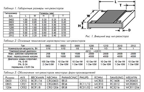
Figura 4. Rezistoare SMD montate la suprafață
Rezistoarele cu cip de cele mai mici dimensiuni sunt produse fără marcaje, deoarece pur și simplu nu există unde să le puneți. Începând de la dimensiunea 0805, un marcaj din trei cifre este plasat pe „spatele” rezistorului. Primele două reprezintă denumirea, iar al treilea este un multiplicator, sub forma unui exponent al numărului 10. Prin urmare, dacă, de exemplu, se scrie 100, atunci va fi 10 * 1 Ohm = 10 Ohm, deoarece orice numărul la puterea zero este egal cu unu, primele două cifre trebuie înmulțite exact cu unu.
Dacă rezistorul spune 103, atunci se dovedește 10 * 1000 = 10 KOhm, iar inscripția 474 spune că avem un rezistor 47 * 10.000 Ohm = 470 KOhm. Rezistoarele cu cip cu o toleranță de 1% sunt marcate cu o combinație de litere și cifre, iar valoarea poate fi determinată doar folosind un tabel care poate fi găsit pe Internet.
În funcție de toleranța rezistenței, valorile rezistenței sunt împărțite în trei rânduri, E6, E12, E24. Valorile denumirilor corespund cifrelor din tabelul prezentat în Figura 5.

Figura 5.
Tabelul arată că, cu cât toleranța de rezistență este mai mică, cu atât mai multe evaluări în rândul corespunzător. Dacă seria E6 are o toleranță de 20%, atunci are doar 6 denumiri, în timp ce seria E24 are 24 de poziții. Dar toate acestea sunt rezistențe uz general. Există rezistențe cu o toleranță de un procent sau mai puțin, astfel încât orice valoare poate fi găsită printre ele.
Pe lângă putere și rezistență nominală, rezistențele au câțiva alți parametri, dar nu vom vorbi despre ei deocamdată.
Conectarea rezistențelor
În ciuda faptului că există destul de multe valori ale rezistențelor, uneori trebuie să le conectați pentru a obține valoarea necesară. Există mai multe motive pentru aceasta: selecția precisă la configurarea circuitului sau pur și simplu lipsa valorii nominale necesare. Practic, se folosesc două scheme de conectare a rezistențelor: în serie și în paralel. Diagramele de conectare sunt prezentate în Figura 6. Acolo sunt date și formule pentru calcularea rezistenței totale.

Figura 6. Scheme de conectare a rezistențelor și formule pentru calcularea rezistenței totale
În cazul unei conexiuni în serie, rezistența totală este pur și simplu suma celor două rezistențe. Este asa cum se vede in poza. De fapt, pot exista mai multe rezistențe. O astfel de includere are loc în . Desigur, rezistența totală va fi mai mare decât cea mai mare. Dacă acestea sunt 1KOhm și 10Ohm, atunci rezistența totală va fi de 1,01KOhm.
Cu o conexiune paralelă, totul este exact invers: rezistența totală a două (sau mai multe rezistențe) va fi mai mică decât cea mai mică. Dacă ambele rezistențe au aceeași valoare, atunci rezistența lor totală va fi egală cu jumătate din această valoare. Puteți conecta o duzină de rezistențe în acest fel, apoi rezistența totală va fi doar o zecime din valoarea nominală. De exemplu, zece rezistențe de 100 ohmi sunt conectate în paralel, apoi rezistența totală este de 100 / 10 = 10 ohmi.
De menționat că într-o conexiune paralelă, conform legii lui Kirchhoff, curentul va fi împărțit în zece rezistențe. Prin urmare, puterea necesară pentru fiecare dintre ele este de zece ori mai mică decât pentru un rezistor.
Continuați să citiți în articolul următor.
Și cum sunt indicate pe schemele electrice. Acest articol va vorbi despre rezistor sau cum o numesc ei la modă veche rezistenţă.
Rezistoarele sunt cele mai comune elemente ale echipamentelor electronice și sunt utilizate în aproape fiecare dispozitiv electronic. Rezistoarele au rezistenta electrica si servesc pentru restricții de flux curentîntr-un circuit electric. Sunt utilizate în circuitele divizor de tensiune, ca rezistențe suplimentare și șunturi instrumente de măsurare, ca regulatoare de tensiune și curent, regulatoare de volum, timbru sonor etc. În dispozitivele complexe, numărul de rezistențe poate ajunge până la câteva mii de bucăți.
1. Parametrii de bază ai rezistențelor.
Parametrii principali ai rezistenței sunt: rezistența nominală, abaterea admisibilă a valorii reale a rezistenței de la valoarea nominală (toleranță), puterea nominală disipată, rezistența electrică, dependența de rezistență: de frecvență, sarcină, temperatură, umiditate; nivelul de zgomot generat, dimensiunea, greutatea și costul. Cu toate acestea, în practică, rezistențele sunt alese în funcție de rezistenţă, puterea nominalăŞi admitere. Să ne uităm la acești trei parametri principali mai detaliat.
1.1. Rezistenţă.
Rezistenţă este o mărime care determină capacitatea unui rezistor de a preveni curgerea curentului într-un circuit electric: cu cât rezistența rezistorului este mai mare, cu atât rezistența pe care acesta o oferă curentului este mai mare și invers, cu atât rezistența rezistorului este mai mică. , cu atât o rezistență mai mică la curent. Folosind aceste calități ale rezistențelor, ele sunt folosite pentru a regla curentul într-o anumită secțiune a circuitului electric.
Rezistența se măsoară în ohmi ( Ohm), kiloohmi ( kOhm) și megaohmi ( MOhm):
1kOhm = 1000 Ohm;
1MΩ = 1000 kΩ = 1000000 Ω.
Industria produce rezistențe de diferite evaluări în domeniul de rezistență de la 0,01 Ohm la 1 GOhm. Valorile numerice ale rezistenței sunt stabilite de standard, prin urmare, la fabricarea rezistenței, valoarea rezistenței este selectată dintr-un tabel special de numere preferate:
1,0 ; 1,1 ; 1,2 ; 1,5 ; 2,0 ; 2,2 ; 2,7 ; 3,0 ; 3,3 ; 3,9 ; 4,3 ; 4,7 ; 5,6 ; 6,2 ; 6,8 ; 7,5 ; 8,2 ; 9,1
Valoarea de rezistență numerică necesară se obține prin împărțirea sau înmulțirea acestor numere cu 10 .
Valoarea nominală a rezistenței este indicată pe corpul rezistenței sub forma unui cod folosind alfanumerice, digital sau codificarea culorilor.

Marcaj alfanumeric.
Când se utilizează marcaje alfanumerice, unitatea de măsură Ohm este desemnată prin literele „ E" Și " R", unitatea kilohm cu litera " LA", și unitatea de megaohm cu litera " M».
a) Rezistoarele cu rezistențe de la 1 la 99 ohmi sunt marcate cu literele „ E" Și " R" În unele cazuri, pe carcasă poate fi indicată doar valoarea completă a rezistenței fără o literă. Pe rezistențele străine, un simbol ohm este plasat după valoarea numerică „ Ω »:
3R— 3 ohmi
10E— 10 ohmi
47R— 47 ohmi
47Ω– 47 ohmi
56
– 56 ohmi

b) Rezistoarele cu rezistențe de la 100 la 999 ohmi sunt exprimate în fracțiuni de kilo-ohm și sunt desemnate cu litera „ LA" În plus, litera care indică unitatea de măsură este plasată în locul zero sau virgulă. În unele cazuri, valoarea totală a rezistenței poate fi indicată cu litera „ R" la sfârșit, sau o singură valoare numerică fără literă:
K12= 0,12 kOhm = 120 ohmi
K33= 0,33 kOhm = 330 ohmi
K68= 0,68 kOhm = 680 ohmi
360R— 360 ohmi

c) Rezistențele de la 1 la 99 kOhm sunt exprimate în kilo-ohmi și notate cu litera „ LA»:
2K0- 2kOhm
10K— 10 kOhm
47K— 47 kOhm
82K— 82 kOhm

d) Rezistențele de la 100 la 999 kOhm sunt exprimate în fracțiuni de megaohm și sunt desemnate cu litera „ M" Litera este plasată în loc de zero sau virgulă:
M18= 0,18 MOhm = 180 kOhm
M47= 0,47 MOhm = 470 kOhm
M91= 0,91 MOhm = 910 kOhm

e) Rezistențele de la 1 la 99 MΩ sunt exprimate în megaohmi și notate cu litera „ M»:
1M- 1 MOhm
10M- 10 MOhm
33M— 33 MOhm

f) Dacă rezistența nominală este exprimată ca număr întreg cu o fracție, atunci literele E, R, LAŞi M, indicând unitatea de măsură, este plasat în loc de virgulă, separând părțile întregi și fracționale:
R22– 0,22 ohmi
1E5— 1,5 ohmi
3R3— 3,3 ohmi
1K2— 1,2 kOhm
6K8— 6,8 kOhm
3M3— 3,3 MOhm

Codarea culorilor.
Codarea culorilor este indicată de patru sau cinci inele colorate și începe de la stânga la dreapta. Fiecare culoare are propria sa valoare numerică. Inelele sunt mutate la unul dintre bornele rezistenței, iar inelul situat chiar la margine este considerat primul. Dacă dimensiunile rezistenței nu permit plasarea marcajului mai aproape de unul dintre borne, atunci lățimea primului inel este de aproximativ două ori mai mare decât celelalte.

Rezistența rezistenței este raportată de la stânga la dreapta. Rezistoarele cu o valoare de toleranță de ±20% (toleranța va fi discutată mai jos) sunt marcate cu patru inele: primele două sunt desemnate în Ohmi, al treilea inel este multiplicator, iar al patrulea mijloc admitere sau clasa de precizie rezistor. Al patrulea inel este aplicat cu un spațiu vizibil față de celelalte și este situat la borna opusă a rezistenței.
Rezistoarele cu o valoare de toleranță de 0,1...10% sunt marcate cu cinci inele de culoare: primele trei sunt valoarea numerică a rezistenței în Ohmi, al patrulea este multiplicatorul, iar al cincilea inel este toleranța. Pentru a determina valoarea rezistenței, utilizați un tabel special.

De exemplu. Rezistorul este marcat cu patru inele:
roșu - ( 2
)
violet - ( 7
)
roșu - ( 100
)
argint - ( 10%
)
Deci: 27 Ohm x 100 = 2700 Ohm = 2,7 kOhmi cu permisiunea ±10%.
Rezistorul este marcat cu cinci inele:
roșu - ( 2
)
violet ( 7
)
roșu ( 2
)
roșu ( 100
)
auriu ( 5%
)
Deci: 272 Ohm x 100 = 27200 Ohm = 27,2 kOhmi cu permisiunea ±5%
Uneori devine dificil să identifici primul inel. Există o regulă de reținut aici: începutul marcajelor nu va începe cu culoarea neagră, aurie și argintie.
Și încă un moment. Dacă nu doriți să vă ocupați de masă, există programe pe Internet calculator online este conceput pentru a calcula rezistența folosind inele colorate. Programele pot fi descărcate și instalate pe un computer sau smartphone. De asemenea, puteți citi despre marcajele de culoare și alfanumerice în articol.
Marcaj digital.
Marcarea digitală este aplicată pe carcasele componentelor SMD și marcată trei sau patruîn cifre.

La trei cifre marcajul, indică primele două cifre valoarea numerică a rezistențeiîn Ohmi, a treia cifră indică factor. Multiplicatorul este numărul 10 ridicat la puterea celei de-a treia cifre:
221
– 22 x 10 la puterea lui 1 = 22 Ohm x 10 = 220 ohmi;
472
– 47 x 10 la puterea lui 2 = 47 Ohm x 100 = 4700 Ohm = 4,7 kOhmi;
564
– 56 x 10 la puterea lui 4 = 56 Ohm x 10000 = 560000 Ohm = 560 kOhm;
125
– 12 x 10 la puterea lui 5 = 12 Ohm x 100000 = 12000000 Ohm = 1,2 MOhm.
Dacă ultima cifră zero, atunci multiplicatorul va fi egal unitate, deoarece zece la puterea zero este egal cu unu:
100
– 10 x 10 la puterea 0 = 10 Ohm x 1 = 10 ohmi;
150
– 15 x 10 la puterea 0 = 15 Ohm x 1 = 15 ohmi;
330
– 33 x 10 la puterea 0 = 33 Ohm x 1 = 33 ohmi.
La patru cifre marcaj, primele trei cifre indică și valoarea numerică a rezistenței în Ohmi, a treia cifră indică multiplicatorul. Multiplicatorul este numărul 10 ridicat la puterea celei de-a treia cifre:
1501
– 150 x 10 la puterea lui 1 = 150 Ohm x 10 = 1500 Ohm = 1,5 kOhm;
1602
– 160 x 10 la puterea lui 2 = 160 Ohm x 100 = 16000 Ohm = 16 kOhm;
3243
– 324 x 10 la puterea lui 3 = 324 Ohm x 1000 = 324000 Ohm = 324 kOhm.
1.2. Toleranța (clasa de precizie) a rezistenței.
Doilea parametru important rezistența este abaterea admisibilă a rezistenței reale de la valoarea nominală și se determină admitere(clasa de precizie).
Abaterea admisibilă este exprimată în la sutăși este indicat pe corpul rezistenței ca cod literă, format dintr-o literă. Fiecărei litere i se atribuie o anumită valoare de toleranță numerică, ale cărei limite sunt determinate de GOST 9964-71 și sunt prezentate în tabelul de mai jos:

Cele mai comune rezistențe vin în toleranțe de 5%, 10% și 20%. Rezistoarele de precizie utilizate în echipamentele de măsurare au toleranțe de 0,1%, 0,2%, 0,5%, 1%, 2%. De exemplu, un rezistor cu o rezistență nominală de 10 kΩ și o toleranță de 10% poate avea o rezistență reală cuprinsă între 9 și 11 kΩ ±10%.
Pe corpul rezistenței, toleranța este indicată după rezistența nominală și poate consta în cod literă sau valoare digitalăîn procente.


Pentru rezistențele cu coduri de culoare, este indicată toleranța dura inel de culoare: argintiu – 10%, auriu – 5%, roșu – 2%, maro – 1%, verde – 0,5%, albastru – 0,25%, violet – 0,1%. Dacă nu există inel de toleranță, rezistența are o toleranță de 20%.
1.3. Putere de disipare nominală.
Al treilea parametru important al unui rezistor este acesta disiparea puterii
Când curentul trece printr-un rezistor, acesta se eliberează energie electrica(putere) sub formă de căldură, care mai întâi crește temperatura corpului rezistenței și apoi trece în aer datorită transferului de căldură. De aceea putere de disipare ei numesc cea mai mare putere de curent pe care un rezistor este capabil să o reziste mult timp și să se disipeze sub formă de căldură fără a compromite pierderea parametrilor săi nominali.
Deoarece o temperatură prea mare a corpului rezistenței poate duce la defecțiunea acestuia, atunci când se realizează circuite, este setată o valoare care indică capacitatea rezistenței de a disipa o anumită putere fără supraîncălzire.
Se ia unitatea de masura a puterii watt(W).
De exemplu. Să presupunem că un curent de 0,1 A trece printr-un rezistor cu o rezistență de 100 ohmi, ceea ce înseamnă că rezistorul disipează 1 W de putere. Dacă rezistența are o putere mai mică, se va supraîncălzi rapid și se va eșua.
În funcție de dimensiuni geometrice rezistențele pot disipa o anumită putere, astfel încât rezistențele de diferite puteri diferă ca mărime: cu cât dimensiunea rezistorului este mai mare, cu atât puterea sa nominală este mai mare, cu atât curentul și tensiunea pe care le poate suporta sunt mai mari.
Rezistoarele sunt disponibile cu putere de disipare de 0,125 W, 0,25 W, 0,5 W, 1 W, 2 W, 3 W, 5 W, 10 W, 25 W și mai mult.

La rezistențele care încep de la 1 W și mai sus, valoarea puterii este indicată pe carcasă ca valoare digitală, în timp ce rezistențele de dimensiuni mici trebuie să fie determinate de „ochi”.

Cu experiență, determinarea puterii rezistențelor de dimensiuni mici nu provoacă dificultăți. La început, îl puteți folosi pe cel obișnuit ca ghid pentru comparație. meci. Puteți citi mai multe despre putere și, în plus, puteți viziona un videoclip în articol.
Cu toate acestea, există o mică nuanță cu dimensiunile care trebuie luate în considerare la efectuarea instalării: dimensiunile rezistențelor interne și externe de aceeași putere sunt ușor diferite unele de altele - rezistențele interne sunt puțin mai mari decât omologii lor străini.
Rezistoarele pot fi împărțite în două grupe: rezistențe rezistență constantă(rezistoare fixe) și rezistențe rezistență variabilă(rezistoare variabile).
2. Rezistoare de rezistență constantă (rezistoare fixe).
Un rezistor este considerat constant dacă rezistența sa rămâne aceeași în timpul funcționării. neschimbat. Din punct de vedere structural, un astfel de rezistor este un tub ceramic, pe suprafața căruia se aplică un strat conductiv, care are o anumită rezistență ohmică. Capacele metalice sunt presate de-a lungul marginilor tubului, la care sunt sudate cablurile de rezistență din sârmă de cupru cositorită. Partea superioară a carcasei rezistenței este acoperită cu email colorat rezistent la umiditate.

Tubul ceramic se numește element rezistiv iar in functie de tipul de strat conductiv aplicat pe suprafata, rezistentele se impart in non-sârmăŞi sârmă.
Rezistoarele fără fire sunt utilizate pentru a funcționa în circuite electrice DC și DC. AC, în care curg curenți de sarcină relativ mici. Elementul rezistiv al rezistorului este realizat sub formă de subțire peliculă semiconductoare, aplicat pe o bază ceramică.
Filmul semiconductor se numește strat rezistivși este realizat dintr-o peliculă dintr-o substanță omogenă cu grosimea de 0,1 - 10 microni (micrometru) sau din microcompoziții. Microcompozițiile pot fi realizate din carbon, metale și aliajele acestora, oxizi și compuși ai metalelor și, de asemenea, sub formă de peliculă mai groasă (50 microni) constând dintr-un amestec zdrobit de substanță conductoare.
În funcție de compoziția stratului rezistiv, rezistențele sunt împărțite în carbon, metal-film (metalizat), metal-dielectric, metal-oxid și semiconductor. Cele mai utilizate pe scară largă sunt rezistențele fixe din peliculă metalică și din compozit de carbon. Rezistoarele domestice includ MLT, OMLT (metalizate, lacuite cu email, rezistente la căldură), BC (carbon) și KIM, TVO (compozit).

Rezistoarele fără fir se caracterizează prin dimensiunea și greutatea lor mică, costul redus și capacitatea de a fi utilizate la frecvențe înalte de până la 10 GHz. Cu toate acestea, nu sunt suficient de stabile, deoarece rezistența lor depinde de temperatură, umiditate, sarcina aplicată, timpul de funcționare etc. Dar totuși, proprietățile pozitive ale rezistențelor fără fir sunt atât de semnificative încât sunt cele mai utilizate pe scară largă.
2.2. Rezistoare bobinate.
Rezistoarele bobinate sunt utilizate în circuitele electrice DC. La realizarea unui rezistor, un fir subțire din nichel, nicrom, constantan sau alte aliaje cu rezistivitate electrică mare este înfășurat pe corpul său în unul sau două straturi. Rezistivitatea ridicată a firului permite ca rezistența să fie realizată cu un consum minim de materiale și dimensiuni reduse. Diametrul firelor utilizate este determinat de densitatea de curent care trece prin rezistor, parametri tehnologici, fiabilitate și cost, și începe de la 0,03 - 0,05 mm.

Pentru a proteja împotriva influențelor mecanice sau climatice și pentru a asigura spirele, rezistența este acoperită cu lacuri și emailuri sau sigilată. Tipul de izolație afectează rezistența la căldură, rezistența dielectrică și diametrul exterior al firului: cu cât diametrul firului este mai mare, cu atât stratul de izolație este mai gros și rigiditatea dielectrică este mai mare.
Cele mai utilizate fire sunt smalțul izolator PE (smalț), PEV (smalț de înaltă rezistență), PETV (smalț rezistent la căldură), PETK (smalț rezistent la căldură), al cărui avantaj este grosimea sa mică, cu o putere electrică destul de mare. rezistenţă. Rezistoarele obișnuite de mare putere sunt rezistoare cu fire emailate, cum ar fi PEV, PEVT, S5-35 etc.

În comparație cu rezistențele fără fir, rezistențele cu fire sunt mai stabile. Ei pot lucra la mai multe temperaturi ridicate, rezista la suprasarcini semnificative. Cu toate acestea, sunt mai dificil de fabricat, mai scumpe și nepotrivite pentru utilizare la frecvențe de peste 1-2 MHz, deoarece au capacitate și inductanță intrinsecă ridicate, care se manifestă deja la frecvențe de câțiva kiloherți.
Prin urmare, ele sunt utilizate în principal în circuitele de curent continuu sau de joasă frecvență, unde sunt necesare o precizie ridicată și stabilitate de funcționare, precum și capacitatea de a rezista la curenți semnificativi de suprasarcină care provoacă supraîncălzirea semnificativă a rezistorului.
Odată cu apariția microcontrolerelor, tehnologia modernă a devenit mai funcțională și, în același timp, mult mai mică. Utilizarea microcontrolerelor a făcut posibilă simplificarea circuite electroniceși, prin urmare, reduce consumul de curent al dispozitivelor, ceea ce a făcut posibilă miniaturizarea bazei elementului. Figura de mai jos arată rezistențele SMD care sunt lipite pe placă din partea plăcii de circuit imprimat.

Pe scheme de circuite Rezistoarele fixe, indiferent de tipul lor, sunt descrise ca dreptunghi, iar bornele rezistoarelor sunt reprezentate ca linii trasate din laturile dreptunghiului. Această denumire este acceptată peste tot, dar în unele circuite străine este utilizată denumirea unui rezistor sub forma unei linii dintate (fierăstrău).

Lângă simbol au pus litera latină „ R" și numărul de serie al rezistenței din circuit și, de asemenea, indică rezistența sa nominală în unități de Ohm, kOhm, MOhm.
Valoarea rezistenței de la 0 la 999 ohmi este indicată în Omaha, dar nu pune o unitate de măsură:
15
— 15 ohmi
680
- 680 ohmi
920
— 920 ohmi
Pe unele diagrame străine este desemnată litera Om R:
1R3— 1,3 ohmi
33R– 33 ohmi
470R— 470 ohmi
Valoarea rezistenței de la 1 la 999 kOhm este indicată în kiloohmi cu adăugarea literei " La»:
1,2k— 1,2 kOhm
10k— 10 kOhm
560k— 560 kOhm
Valorile rezistenței de 1000 kOhm și mai mult sunt indicate în unități megaohm cu adăugarea literei " M»:
1M- 1 MOhm
3,3 milioane— 3,3 MOhm
56M— 56 MOhm

Rezistorul se foloseste in functie de puterea pentru care este proiectat si pe care o poate rezista fara riscul de a fi deteriorat la trecerea prin el curent electric. Prin urmare, pe diagramele din interiorul dreptunghiului ei scriu simboluri, indicând puterea rezistorului: o bară oblică dublă indică o putere de 0,125 W; o linie dreaptă de-a lungul pictogramei rezistor indică o putere de 0,5 W; Cifrele romane indică puterea de la 1 W și mai mult.


4. Conectarea în serie și paralelă a rezistențelor.
Foarte des apare o situație când, la proiectarea unui dispozitiv, nu există nici un rezistor cu rezistența necesară la îndemână, dar există rezistențe cu alte rezistențe. Totul este foarte simplu aici. Cunoscând calculul conexiunilor în serie și paralele, puteți asambla un rezistor cu orice valoare.
La secvenţial conectarea rezistențelor rezistența lor totală Rtot egală cu suma tuturor rezistențelor rezistențelor conectate în acest circuit:
Rtotal = R1 + R2 + R3 + … + Rn
De exemplu. Dacă R1 = 12 kOhm și R2 = 24 kOhm, atunci rezistența lor totală Rtot = 12 + 24 = 36 kOhm.

La paralel Când rezistențele sunt conectate, rezistența lor totală scade și este întotdeauna mai mică decât rezistența fiecărui rezistor individual:
![]()
Să presupunem că R1 = 11 kOhm și R2 = 24 kOhm, atunci rezistența lor totală va fi egală cu:
Și încă un punct: atunci când două rezistențe cu aceeași rezistență sunt conectate în paralel, rezistența lor totală va fi egală cu jumătate din rezistența fiecăruia dintre ele.

Din exemplele de mai sus este clar că dacă vor să obțină un rezistor cu o rezistență mai mare, atunci folosesc o conexiune în serie, iar dacă cu o rezistență mai mică, atunci o conexiune paralelă. Și dacă aveți întrebări, citiți articolul, care descrie metodele de conectare mai detaliat.
Ei bine, pe lângă ceea ce ați citit, urmăriți un videoclip despre rezistențele de rezistență constantă.
Ei bine, asta este practic tot ce am vrut să spun despre rezistor în general și separat despre rezistențe constante. În a doua parte a articolului ne vom familiariza.
Noroc!
Literatură:
V. I. Galkin - „Pentru un radioamator începător”, 1989
V. A. Volgov - „Piese și componente ale echipamentelor radio-electronice”, 1977
V. G. Borisov - „Tânărul amator de radio”, 1992
Conductorii oferă rezistență la curentul electric, cu cât rezistența este mai mare, cu atât puterea curentului electric prin conductor este mai mică. Rezistența unui conductor depinde de materialul din care este compus, lungime, secțiune transversală și temperatură. Cu cât conductorul este mai lung, cu atât este mai mare rezistența; Cu cât conductorul este mai subțire, cu atât este mai mare rezistența;
Rezistența este indicată prin literă R, iar unitatea de rezistență este scrisă cu litere Ohm. În practică, se folosesc și unități de rezistență electrică: kiloohmi ( kOhm) și megaohm ( MOhm).
1 kOhm = 1000 Ohm
1 Mohm = 1000000 Ohm
Pentru a găsi rezistența unui conductor în ohmi, trebuie să împărțiți tensiunea de la capetele sale în volți la curentul în amperi:
Rezistori fixe
Un rezistor este un element pasiv al unui circuit electric. Servește la reducerea curentului în timpul funcționării, rezistențele se încălzesc, deoarece energia electrică în exces este transformată de rezistențe în căldură. Pe schemele de circuite electrice, rezistențele sunt afișate ca un dreptunghi cu două terminale sau ca o linie întreruptă (standard american), desemnată prin litera R cu un număr de serie (R1, R2 etc.). Valoarea rezistorului este indicată lângă acesta.

Parametrul principal al unui rezistor este rezistența. Rezistența rezistenței este măsurată în ohmi, kilo-ohmi, mega-ohmi. Puterea nominală de disipare a rezistenței (de la 0,05 la 5 W) este indicată prin semne speciale plasate în interiorul simbolului.

Marcaje de rezistență. Conform GOST 2.702-75, rezistențele de la 0 la 999 ohmi sunt indicate pe diagrame printr-un număr fără unitate de măsură (3,3; 47; 220; 750 etc.), de la 1 la 999 kOhm - printr-un număr cu litera k (47 k; 330 k; 910 k etc.), peste 1 megaohm - un număr cu litera M (1 M; 4,7 M etc.).
Conform GOST 11076-69, unitățile de rezistență din sistemul codificat sunt desemnate prin literele E sau R (Ohm), K (kilo-ohm) și M (mega-ohm). Deci 33 de ohmi sunt etichetați 33E, 1 ohmi - 1R0, 47 ohmi - 47E, 10 kOhmi - 10K, 47 kOhmi - 47K etc.
Rezistențele de la 100 la 1000 ohmi și de la 100 la 1000 kOhmi sunt exprimate în fracțiuni de kilo-ohm și, respectiv, mega-ohm, iar unitatea de măsură corespunzătoare este pusă în locul zero și virgulă: 150 Ohm = 0,15 kOhm = K150; 910 Ohm=0,91 kOhm=K91; 180 kOhm = 0,18 MOhm = M18; 680 kOhm=0,68 MOhm=M68 etc.
Dacă rezistența nominală este exprimată ca un întreg cu o fracție, atunci unitatea de măsură este plasată în locul punctului zecimal: 3,3 Ohm - 3E3 sau 3R3; 4,7 kOhm – 4K7; 3,3 MOhm – 3M3 etc.
Rezistoarele și trimmerele SMD pot fi marcate cu trei numere, primele două indică rezistența în ohmi (mantișă), iar al treilea - numărul de zerouri ulterioare (exponent la baza 10), iar litera R poate fi adăugată la marcaj la indica virgulă zecimală Exemple:
Marcarea 513 înseamnă 51 x 10 3 = 51000 ohmi sau 51 kohmi
Marcajul R470 înseamnă 0,47 Ohm
Există încă multe marcaje cu dungi colorate, dar producătorii de rezistențe nu respectă în prezent un standard general, așa că este mai fiabil să măsori rezistența rezistențelor cu un multimetru.
Rezistoare variabile
Rezistoarele variabile sunt rezistențe a căror rezistență poate fi modificată. Folosit ca comenzi pentru câștig, volum, ton etc.

Există două scheme pentru includerea rezistențelor variabile într-un circuit electric. Într-un caz, ele sunt folosite pentru a regla curentul într-un circuit, iar apoi rezistența reglabilă se numește reostat. Într-un alt caz, ele sunt folosite pentru a regla tensiunea, apoi rezistorul se numește potențiometru.
Rezistori trimmer
Un tip de rezistențe variabile este reglarea. Unitatea de control pentru astfel de rezistențe este adaptată pentru a controla o șurubelniță.

Conectarea rezistențelor
Când rezistențele sunt conectate în serie, rezistențele lor se adună:

Cu o conexiune paralelă, rezistența totală este calculată folosind formula:

Când două rezistențe identice sunt conectate în paralel, rezistența totală va fi egală cu jumătate din rezistența unuia dintre ele.
În acest fel, puteți obține valorile rezistoarelor necesare din cele disponibile.
Rețelele electrice necesită prezența rezistenței, astfel încât în ele sunt instalate elemente pasive sub formă de rezistențe. Și când apare întrebarea - marcarea rezistenței - aceasta este direct legată de marcarea rezistenței. La urma urmei, este pur și simplu imposibil să determinați acest parametru al acestui element fără a avea un multimetru la îndemână. De aceea au fost adoptate standardele de etichetare. Sunt două dintre ele: numerice și color.
Numerice și alfabetice
Literele și cifrele erau folosite în perioada respectivă Uniunea Sovietică. Aceste vremuri s-au scufundat în uitare, dar rezistențele sovietice rămân și sunt folosite și astăzi. Pentru a înțelege mărcile, să dăm câteva exemple.
În primul rând, trebuie să faci față puterii. Este indicat în wați și este criptat în marca elementului. De exemplu, MLT-1. Acesta este un rezistor cu peliculă metalică, lăcuit și rezistent la căldură, cu o putere de 1 watt.
Cu rezistență, lucrurile sunt puțin mai complicate. Aici este folosită denumirea literei alfabetului latin, care determină rangul.
- „R” și „E” sunt măsurători în Ohmi;
- „K” înseamnă kiloohmi (kΩ);
- „M” megaohmi (mOhmi).
De exemplu, 47E sau 47R este un rezistor de 47 ohmi. Sau 47K este o rezistență egală cu 47 kOhm. Sau 1M este un megaohm. Apropo, trebuie remarcat faptul că numerele și literele pot fi plasate invers, adică litere în fața numerelor: K47 este 47 kOhm sau 470 Ohm. Dacă valoarea rezistenței nu este un număr întreg, atunci numerele, ca de obicei, sunt separate prin virgulă: 4,3K = 4,3 kOhm. În unele mărci, în loc de virgulă, poate exista o literă: 4K3 = 4,3 kOhm.
În fotografia de mai jos puteți vedea exact ultimul marcaj, egal cu 1 kOhm și notat cu 1K0:

Culoare
Simbolurile alfabetice și numerice au dispărut; marcajele de rezistență moderne sunt colorate. Sau, mai precis, constă din dungi colorate care sunt aplicate în jurul circumferinței corpului elementului. Pot exista de la trei până la șase astfel de dungi.
Această denumire a fost creată pentru a facilita citirea parametrilor nominali ai rezistenței, indiferent de locația și poziția de instalare a acestuia. Deși trebuie spus că marea varietate de marcaje de culoare creează dificultăți în reamintirea culorii designului. Prin urmare, pe Internet există multe calculatoare online cu ajutorul cărora puteți determina cu ușurință caracteristicile rezistențelor. Trebuie doar să introduceți în ele culorile indicate de dungi. Ca rezultat, calculatorul va afișa parametrul elementului.
Marcajul de culoare este împărțit la numărul de dungi:
- trei dungi sunt o desemnare cu o precizie de 20%;
- patru este o precizie de 5% sau 10%;
- cinci este o precizie de 0,005%.

Un rezistor cu șase benzi este un element ale cărui marcaje includ TCR (coeficient de temperatură al rezistenței). Să ne uităm la fiecare poziție separat.
Trei dungi
Ce înseamnă acest marcaj de culoare:
- primele două dungi colorate sunt o desemnare numerică;
- al treilea este numărul de zerouri.
Patru
Totul este la fel aici. Singura diferență este a patra dungă, care poate fi fie aurie, fie argintie. Indică precizia, care corespunde aurului - 5%, argintului - 10%.
Să dăm un exemplu bazat pe figura de mai jos:

Aici prima culoare este roșu, care corespunde numărului „2”. Al doilea violet este „7”. Al treilea galben este „4”. Marcajul final de culoare este auriu (precizie de 5%). Ca rezultat, se dovedește că un rezistor cu acest marcaj are o rezistență de 270.000 ohmi sau 270 kOhmi.
Desemnare cu cinci benzi
Acest marcaj de culoare determină rezistența în echivalentul numeric al primelor trei dungi. Al patrulea este numărul de zerouri din spatele unui număr de trei cifre. A cincea este acuratețea.
Un alt exemplu bazat pe imagine:

Albastru – 6, roșu – 2, verde – 5, maro – 10, auriu – 5%. Adică acest dispozitiv are o rezistență de 6250 Ohmi sau 6,25 kOhmi.
Desemnare cu șase benzi
Aici totul este exact la fel ca în cazul precedent, se adaugă doar o a șasea bandă, indicând coeficientul de temperatură de rezistență. Determină modul în care s-ar putea schimba rezistența (în părți pe milion) dacă regim de temperatură funcţionarea cu un grad. Unitatea sa de măsură este ppm/ºC. Apropo, abrevierea „ppm” înseamnă „parte per milion”, ceea ce înseamnă „părți pe milion”.
Desemnarea rezistențelor mai mici de 10 ohmi
Marcarea culorii elementelor cu o rezistență mai mică de 10 ohmi necesită Informații suplimentare, conținut în modele de culoare suplimentare. Chestia este că numărul standard de dungi și culorile lor nu pot descrie cu exactitate un rating de mai puțin de zece ohmi.

Prin urmare, li se adaugă o a treia dungă, care are două culori - auriu și argintiu. Primul corespunde cu numărul 0,1, al doilea cu numărul 0,01. Celelalte benzi sunt desemnate ca de obicei. Pentru un exemplu, să revenim la secțiunea corespunzătoare, unde ne-am uitat la exemplul cu un model în patru culori. Indică: roșu - 2, violet 7, a treia dungă, de exemplu, va fi aurie. Aceasta înseamnă că rezistența rezistorului va fi:
27*0,1=2,7 ohmi.
Să vă reamintim încă o dată că marcajul de culoare include acuratețea indicatorului de rezistență. După cum am menționat mai sus, este indicat fie printr-o dungă aurie, fie argintie. Sunt folosite cel mai des. Dar mai sunt două culori: roșu - 2% și maro - 1%.
În primul rând, să ne ocupăm de rezistențele sovietice.
Indiferent ce faci, nu poți scăpa de electronicele sovietice. Prin urmare, puțină teorie nu vă va face rău.
La prima vedere, trebuie să estimăm ce putere maximă poate disipa rezistorul. De sus în jos, mai jos în fotografie, rezistențe după putere: 2 Watt, 1 Watt, 0,5 Watt, 0,25 Watt, 0,125 Watt. Pe rezistențele cu o putere de 1 și 2 wați scriu MLT-1 și, respectiv, MLT-2.

MLT este un tip al celor mai comune rezistențe sovietice, de la nume prescurtate M folie metalica, L lacuit, T rezistent la caldura. Pentru alte rezistențe, puterea poate fi estimată pe baza dimensiunilor acestora. Cu cât este mai mare rezistența, cu atât mai multă putere poate disipa în spațiul înconjurător.
Unitățile de măsură în MLT - Ohmi - sunt desemnate ca R sau E. Kilo-ohmi - cu litera „K”, Mega-ohmi cu litera „M”. Totul este simplu aici. De exemplu, 33E (33 ohmi); 33R (33 ohmi); 47K (47 kOhm); 510K (510 kOhm); 1,0 M (1 MOhm). Există, de asemenea, un truc că literele pot preceda numerele, de exemplu, K47 înseamnă că rezistența este de 470 ohmi, M56 - 560 kilohmi. Și uneori, ca să nu se deranjeze cu virgule, împing prostește o literă acolo, de exemplu. 4K3 = 4,3 Kilohmi, 1M2 – 1,2 Megaohmi.
Să ne uităm la eroul nostru. Să ne uităm imediat la denumire. 1K0 sau în cuvintele „unu și zero”. Aceasta înseamnă că rezistența sa ar trebui să fie de 1,0 Kilohm.
.JPG)
Să vedem dacă acest lucru este cu adevărat adevărat?
.JPG)
Ei bine, da, totul este de acord cu o mică eroare.
Codarea culorilor a rezistențelor
Pentru a determina valoarea rezistenței unui rezistor cu coduri de culori, trebuie mai întâi să îl rotiți astfel încât dungile argintii sau aurii să fie în dreapta și un grup de alte benzi în stânga. Dacă nu puteți găsi o bandă de argint sau aur, atunci trebuie să rotiți rezistența, astfel încât grupul de benzi să fie pe partea stângă.
Culoarea benzii este un număr codificat:
Negru - 0
Maro - 1
Roșu - 2
Portocaliu - 3
Galben - 4
Verde - 5
Albastru – 6
Mov - 7
Gri - 8
Alb – 9
A treia bară are o semnificație diferită: indică numărul de zerouri care ar trebui adăugat la valoarea digitală anterioară obținută.
Culoare dungi – Număr de zerouri
Negru - Fără zerouri -
Maro – 1 – 0
Roșu – 2 – 00
Portocaliu – 3 – 000
Galben – 4 – 0000
Verde – 5 – 00000
Albastru – 6 – 000000
Violet – 7 – 0000000
Gri – 8 – 00000000
Alb – 9 – 000000000
Trebuie amintit că codificarea culorilor este destul de consistentă și logică, de ex. verdeînseamnă fie valoarea 5 (pentru primele două dungi) fie 5 zerouri (pentru a treia bandă).
Secvența de culori în sine coincide cu succesiunea de culori din curcubeu (de la roșu la culori violete) (!!!)
Dacă un rezistor are un grup de patru benzi în loc de trei, atunci primele trei dungi sunt numere, iar a patra bandă indică numărul de zerouri. A treia bandă digitală face posibilă indicarea rezistenței rezistenței cu o precizie mai mare.
Să ne uităm la un rezistor necunoscut nouă.
.JPG)
Practic, există trei, patru, cinci și chiar șase dungi pe un rezistor. Prima bandă este cea mai apropiată de terminalul rezistenței și este mai lată decât toate celelalte benzi, dar uneori această regulă nu este respectată. Pentru a nu verifica cărțile de referință despre marcarea culorii rezistențelor, puteți descărca multe programe diferite de pe Internet pentru a determina valoarea rezistenței.
De asemenea, puteți găsi un calculator online foarte bun .
Calculator de marcare a rezistenței
Mi-a plăcut foarte mult programul. Chiar și un preșcolar poate înțelege acest program. Să-l folosim pentru a determina valoarea rezistenței noastre. Intrăm în benzile rezistenței care ne interesează și programul ne va da valoarea lui.
.jpg)
Și în stânga jos în cadru vedem valoarea rezistenței: 1kOhm -+5%. Convenabil nu?
Acum să măsurăm rezistența folosind un multimetru: 971 ohmi. 5% din 1000 ohmi sunt 50 ohmi. Aceasta înseamnă că valoarea rezistenței trebuie să fie în intervalul de la 950 ohmi la 1050 ohmi, altfel poate fi considerată nepotrivită. După cum putem vedea, valoarea de 971 ohmi se încadrează perfect în intervalul de la 950 la 1050 ohmi. În consecință, am determinat corect valoarea rezistorului și poate fi folosit în siguranță pentru scopurile noastre.
.JPG)
Să exersăm și să determinăm valoarea unui alt rezistor.
.JPG)
.jpg)
.JPG)
Totul este OK ;-).
Marcarea rezistențelor SMD
Marcarea digitală a rezistențelor
Să ne uităm la marcajele rezistențelor. Rezistoarele de dimensiunea 0402 (valori de dimensiune) nu sunt marcate. Restul sunt marcate cu trei sau patru numere, deoarece sunt puțin mai mari și încă mai puteți pune numere sau un fel de marcaj pe ele. Rezistoarele cu o toleranță de până la 10% sunt marcate cu trei cifre, unde primele două cifre indică valoarea acestui rezistor, iar ultima a treia cifră este 10 la puterea acestei ultime cifre. Să ne uităm la acest rezistor:
.jpg)
Rezistența rezistorului prezentat în fotografie este 22x10 2 = 2200 ohmi sau 2,2 K.
Să verificăm dacă este adevărat? Luăm această componentă SMD minusculă între sonde și măsurăm rezistența.
.JPG)
Rezistenta 2,18 kOhm. O mică eroare nu contează.
Rezistoarele SMD cu o toleranță de 1% și dimensiunea 0805 și mai mare sunt marcate cu patru numere. De exemplu, un rezistor cu numărul 4422. Acesta este calculat ca 442x10 2 = 44200 Ohm = 44,2 kOhm.
Există și rezistențe SMD cu rezistență aproape nulă (mai există o rezistență foarte, foarte mică) sau pur și simplu așa-zișii jumperi. Arată mai plăcut din punct de vedere estetic decât orice fire.

Codarea rezistențelor este cea mai comună practică în zilele noastre. Uneori dai peste rezistențe ale căror marcaje arată foarte ciudat. Nu vă alarmați, acesta este un cod simplu de marcare care este folosit de unii producători de componente electronice. Ar putea arăta cam așa:

sau chiar asa:

Cum se determină valoarea rezistenței unor astfel de rezistențe? Pentru aceasta, există un tabel cu care puteți determina cu ușurință valoarea oricărui rezistor cu un marcaj de cod. Aşa, primele două cifre conțin valoarea secretă a rezistenței, iar litera este multiplicatorul.
Iată tabelul real:

Litere: S=10 -2; R=10-1; A=1; B= 10; C=102; D=103; E=104; F=10 5
Aceasta înseamnă că rezistența acestui rezistor este
vom avea 140x10 4 = 1,4 MegaOhm.
Și rezistența acestui rezistor
vom avea 102x10 2 = 10,2 KiloOhm.
În programul Rezistor 2.2 puteți găsi cu ușurință coduri și marcaje digitale ale rezistențelor.
Alegerea branding-ului BOURNS 

Plasați marcatorul pe „3 caractere”. Și introducem codul nostru de marcare. De exemplu, același rezistor marcat 15E. Mai jos, în stânga în cadru, vedem valoarea rezistenței acestui rezistor: 1,4 Megaohmi.